What is Injection Molding: 10 Essential Insights for U.S. Buyers
Learn what is injection molding, how it works, and best practices for buyers in the United States.
Injection molding is a manufacturing process that produces parts by injecting molten material into a mold cavity, solidifying, and then ejecting the finished part. This process enables high-volume, precise, and consistent production of plastic components used in automotive, consumer, and industrial applications.
Introduction
What is injection molding and why should U.S. buyers care?
Injection molding is a highly efficient process for producing plastic parts, from tiny connectors to large industrial components. Buyers in the United States often seek suppliers who can deliver consistent quality, scalable production, and cost-effective solutions.
In this guide, you will learn:
- The fundamentals of injection molding
- Key types and materials used
- How to select a supplier and design parts for success
- Common pitfalls and mistakes to avoid
By the end, you’ll have a clear understanding of injection molding and actionable insights for making informed purchasing decisions.
What is Injection Molding?
Injection molding is a manufacturing process that produces parts by injecting molten material into a mold, cooling, and ejecting the solidified component.
The process allows for high-volume, precise, and repeatable production of complex shapes, making it ideal for plastic components in industries such as automotive, electronics, and consumer goods.
- Can produce complex geometries with tight tolerances
- Supports a wide variety of thermoplastics and thermosets
- Enables high-volume production with minimal labor
- Reduces material waste through precise molding
- Parts can be colored, textured, or reinforced
Sources: Plastics Industry Association (PIA, 2023)
How Does Injection Molding Work?
Injection molding works by melting plastic pellets, injecting the molten material into a mold, and then cooling it into the desired shape.
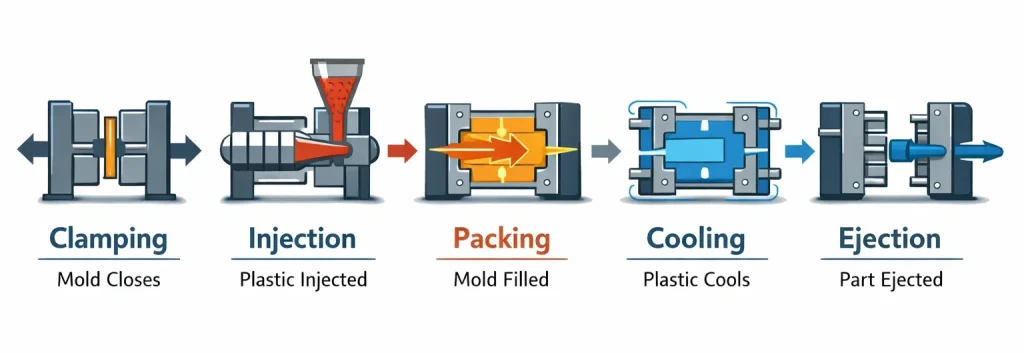
The process has four primary stages:
- Clamping: The mold is closed and securely clamped to withstand injection pressure.
- Injection: Molten plastic is injected into the mold cavity under high pressure.
- Cooling: The material solidifies while taking the shape of the mold.
- Ejection: The finished part is released using ejector pins.
Important Considerations:
- Mold temperature affects surface finish and cycle time.
- Injection pressure and speed determine part integrity.
- Material choice impacts strength, flexibility, and appearance.
Types of Injection Molding
Injection molding comes in multiple types depending on the material and part requirements.
| Type | Material | Best Use Case | Key Benefit |
|---|---|---|---|
| Thermoplastic Injection Molding | ABS, Polypropylene, Nylon | Consumer goods, automotive parts | High-volume production, recyclable materials |
| Thermoset Injection Molding | Epoxy, Phenolic | Electrical components | Heat-resistant, chemically stable |
| Liquid Silicone Rubber (LSR) Injection | Silicone | Medical, food-grade products | Flexible, heat-resistant, precise molding |
| Two-Shot / Multi-Material Injection | Multiple plastics | Parts with soft-touch surfaces or multiple colors | Combines materials in a single cycle |
Materials Used in Injection Molding
Choosing the right material is essential for part performance and durability.
- ABS: Strong, impact-resistant, ideal for housings
- Polypropylene: Lightweight, chemical-resistant, common in consumer goods
- Nylon: High strength, wear-resistant, used in automotive
- Polycarbonate: Transparent, tough, used for lenses and electronics
Tips for Buyers: Check supplier datasheets for mechanical properties, thermal resistance, and FDA compliance if applicable.
Injection Molding Equipment
The right injection molding machine ensures accuracy, efficiency, and repeatability.
- Hydraulic Machines: Strong clamping, widely used
- Electric Machines: Energy-efficient, precise control
- Hybrid Machines: Combines hydraulic strength with electric precision
Machine selection depends on part size, complexity, and production volume.
How to Design Parts for Injection Molding
Successful injection-molded parts require careful design consideration.
- Uniform Wall Thickness: Avoid warping and shrinkage.
- Draft Angles: Facilitate easy part ejection.
- Ribs and Supports: Increase strength without thickening walls.
- Avoid Sharp Corners: Reduces stress concentrations.
- Gate Placement: Ensures even material flow.
Design for manufacturability (DFM) improves quality and reduces costs.
Common Mistakes in Injection Molding
Buyers and designers often make mistakes that increase costs and reduce part quality.
- Overcomplicating part geometry
- Ignoring material shrinkage
- Poor mold maintenance
- Incorrect gate placement
- Underestimating cooling time
Tip: Avoiding these pitfalls saves production time and ensures consistent product quality.
How to Select an Injection Molding Supplier
Choosing the right supplier is critical for quality, cost, and delivery.
- Evaluate Experience: Check industry-specific expertise.
- Inspect Equipment: Ensure modern, well-maintained machines.
- Request Prototypes: Validate part quality before full production.
- Review Quality Systems: ISO-certified suppliers reduce defects.
- Negotiate Terms: Include lead times, pricing, and post-production support.
Cost Considerations in Injection Molding
Injection molding costs depend on material, mold complexity, and production volume.
- Tooling Costs: Initial mold creation can be expensive
- Material Costs: Type and quantity of plastic affect pricing
- Production Costs: Cycle time, labor, and machine type matter
- Post-Processing: Trimming, painting, or assembly adds cost
High-volume production reduces per-part costs significantly.
Comparing Injection Molding vs Other Manufacturing Methods
| Feature | Injection Molding | 3D Printing | CNC Machining |
|---|---|---|---|
| Volume Efficiency | High | Low | Medium |
| Precision | High | Medium | High |
| Material Options | Broad | Limited | Broad |
| Surface Finish | Excellent | Variable | Excellent |
| Cost per Part | Low (high volume) | High | Medium |
Injection molding is most cost-effective for large-scale, repeatable parts.
Advantages of Injection Molding
- High-volume production efficiency
- Excellent repeatability and tolerance control
- Ability to produce complex shapes and fine details
- Material flexibility and recyclability
- Reduced labor requirements
Limitations of Injection Molding
- High upfront tooling costs
- Long lead times for mold production
- Less flexible for rapid design changes
- Material restrictions for extreme temperatures
Key Takeaways
- Injection molding is a process that injects molten material into a mold to produce consistent parts.
- It is ideal for high-volume production of plastic components.
- Proper material selection and design are critical for quality.
- Choosing an experienced supplier minimizes defects and production delays.
- Costs are high upfront but scale efficiently for large orders.
- Avoid common pitfalls such as poor wall design or improper gate placement.
Frequently Asked Questions
- What is the difference between thermoplastic and thermoset injection molding?
- Thermoplastics can be melted and reshaped multiple times, while thermosets harden permanently and resist heat and chemicals.
- How long does it take to produce injection-molded parts?
- Cycle times typically range from 15 seconds to several minutes, depending on part size, material, and mold complexity.
- Can injection molding produce multi-colored parts?
- Yes, using two-shot or multi-material injection molding, multiple colors or materials can be combined in a single part.
- What materials are FDA-approved for injection molding?
- Materials such as polypropylene, polyethylene, and certain grades of ABS are FDA-approved for food and medical applications.
- Is prototyping necessary before full production?
- Yes, prototypes help validate design, detect flaws, and ensure mold performance before committing to mass production.
- How do I maintain molds for consistent quality?
- Regular cleaning, inspection, lubrication, and preventive maintenance prevent wear, defects, and dimensional inconsistencies.
- Can I use injection molding for small production runs?
- It is possible but often less cost-effective due to high tooling costs; alternatives like 3D printing may be better for low volumes.
Suggested Links
Internal:
External:

